DMV MB-VEF 407-412 B01 Dungs Vietnam ,DMV MB-VEF 407-412 B01 Dungs COMBUSTION CONTROLS Vietnam
Nhà cung cấp: Pitesco
Hãng sản xuất: DUNGS , DUNGS COMBUSTION CONTROLS
 Mr. Hà
 live:ha_1652
DUNGS , DUNGS Vietnam , DUNGS Viet nam , DUNGS COMBUSTION CONTROLS , DUNGS COMBUSTION CONTROLS Vietnam
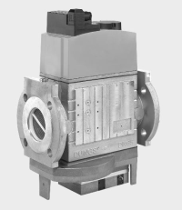
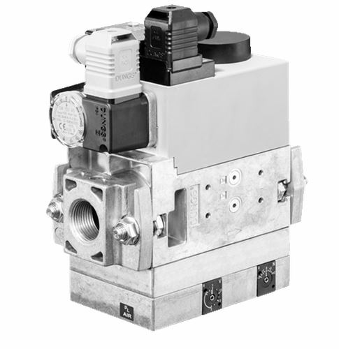
Technical description
The DUNGS GasMultiBloc MB-VEF ... B01 integrates filter, gas-air ratio controls, valves and pressure switches in one compact
fitting:
- Dirt trap: Fine mesh-sieve
- Solenoid valves up to 360 mbar as per
DIN EN 161 Class A Group 2
- Sensitive adjustment of gas and air pressure ratio
- Servo pressure regulator as per DIN EN
88 Class A Group 2; EN 12067-1
- High flow values at low pressure drop
-
Ratio V = p
Br
/ p
L
0.75 : 1 ... 3 : 1
- Zero point correction N possible
-
External pulse lines
- Interference degree N
- Flange connections with pipe threads as
per ISO 7/1
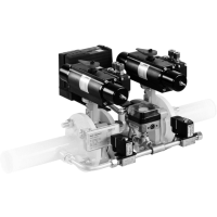
The modular system permits individual solu
-
tions using valve proving system, min./max.
pressure switch, pressure limiter.
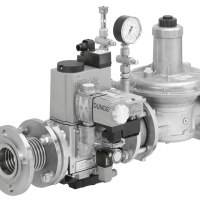
Application
The gas-air ratio control enables the optimum mixture formation for forced air burners and premix burners; this applies for modulating and two-stage variable operating modes.
Suitable for gases of families 1, 2, 3 and other neutral gaseous media.
Approvals
EC type testing certificate as per:
•
EC-Gas Appliances Regulation
•
EC-Pressure Equipment Directive
Approvals in other important gas consuming countries.
Flange, line sockets, pulse lines and screw unions are
not
contained in the scope of supply
Edition 01.18 • Nr. 219 543
2 ... 8
Functional description
Gas flow
1. If the valves V1 and V2 are closed,
chamber a is under input pressure
up to the double seat of valve V1.
2. A hole in the filter housing of MB
407/412 connects min. pressure
switch with chamber a. If the input
pressure applied to the pressure
switch exceeds the incoming refer
-
ence value, it switches through to the
automatic burner control.
3. After release by the automatic burner
control, valves V1 and V2 open.
The gas flow through chambers
a, b and c of the MultiBloc is then released.
Operating method of valve-regula
- tor combination on valve V1
A regulator compensated for residual pressure is integrated in valve V1 (pressure regulating part).
Anchor V1 is not connected with the valve plate unit. When it opens, the anchor pretensions the pressure spring
and releases the valve plate unit.
When the valve closes, the anchor acts directly on the valve plate unit.
Valves V1 and V2 are released at the same time.
In closed position valve V3 blocks the pressure chamber under working diaphragm M against input pressure pe
in
chamber a.
The pressure under working diaphragm
M is defined by a variable flow cross-
section D. The comparison diaphragms
for burner pressure p
Br
and blower
pressure p
L
are interconnected via a
rod. Moving the bearing point sets the
ratio V.
Zero point correction N acts on this rod.
The ambient pressure p
amb
or the firing
chamber pressure p
F
must be applied
to the opposite side of the comparison
diaphragms. Firing chamber pressure
has a reducing effect on the burner
pressure at a ratio of V > 1.
Changes resulting from the force
equilibrium lead to a modification of
the flow cross-section D downstream
of valve V4. Pressure under the work
-
ing diaphragm is re-adjusted and the
valve plate unit V1 changes the free
cross-section.
Operating method of valve V2
The anchor of valve V2 is connected
with the valve plate unit. When it opens,
the anchor pretensions the pressure
spring. Valve V2 opens completely and
without delay.
Block diagram MB-VEF
Valve V4 is activated by valve V2. In
closed position, valve V4 blocks the
chamber under the working diaphragm
M from the burner pressure.
Closing function
When the supply voltage of the main
valve solenoid coils is interrupted, the
valves are closed within < 1 s by the
compression springs.
Pressure taps, gas train diagram
p
Br
Burner pressure
p
F
Firing chamber pressure
p
amb
Ambient pressure
p
L
Blower pressure
1, 3, 4, 5
G 1/8 screw plug
2
Test nipples
6,7,8
Pulse lines p
L
, p
F
, p
Br
V1
Main valve 1
V2
Main valve 2
V3
Control valve 3
V4
Control valve 4
M
Working diaphragm
D
Throttling point
V
Ratio setting
N
Zero point correction
a, b, c
Pressure chambers in flow
direction
N
p
Br
p
L
V
p
F
p
amb
V1
V2
V3
V4
c
b
a
3
4
5
9
8
7
D
M
Gas-air ratio control part
1
2
6
5
4
4
2
p , extern
PN1, DN 4
min. 5 x DN
p
p
a
p
a
Br
F
p
L
3
p
e
3
p
e
7
8
4
6
1
5
1
3
3
4
2
2
6
8
7
3 ... 8
Specifications
Nominal diameters
Flange with pipe threads as per
ISO 7/1 (DIN 2999)
Max. operating pressure
Input pressure ranges
Guiding range
Burner pressure range
Media
Ambient temperature
Dirt trap unit
Pressure switch
Servo pressure regulator
Ratio setting range V
Zero point correction N
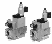
Solenoid valves V1, V2
Measuring
Burner pressure monitor p
Br
Pulse and connection lines
Voltage/frequency
Electrical connection
Rating/power consumption
Switch-on duration
Protection type
Interference suppression
Materials of gas-wetted parts
Installation position
MB-VEF 407 B01
MB-VEF 412 B01
Rp 1/2, 3/4
Rp 1, 1 1/4
and their combinations
and their combinations
360 mbar
MB-...VEF S10/12
p
e
: 5 mbar to 100 mbar
MB-...VEF S30/32
p
e
: 100 mbar to 360 mbar
p
L
: 0.4 to 100 mbar
p
Br
: 0.5 to 100 mbar
Gases of families 1, 2, 3 and other neutral gaseous media
-15 °C to +70 °C (Do not operate MB-VEF below 0 °C in liquid gas systems. Only
suitable for gaseous liquid gas, liquid hydrocarbons destroy sealing materials)
Fine mesh-sieve.
Replacement only possible by dismounting the fitting.
Types GW...A5, ÜB...A2 / NB...A2 to DIN EN 1854 may be attached.
For further information, refer to Datasheets 5.02 and 5.07 “Pressure Switches
for DUNGS Multiple Actuators”
Pressure regulator compensated for residual pressure, leakproof seal when switched
off by means of valve V1 as per DIN EN 88 Class A, Group 2; EN 12067-1
Gas-air ratio control with adjustable ratio V as well as zero point correction N
and firing chamber pressure connection.
Ratio V = p
Br
/ p
L
0.75 : 1 ... 3 : 1; other ratios on request
Possible
Valves as per DIN EN 161 Class A Group 2, fast closing, fast opening
G 1/8 DIN ISO 228, on inlet and outlet flange, on both sides downstream of
dirt trap, on both sides between valves. (pressure switch mounting can partly
exclude measuring)
Downstream of valve V2, pressure switch ...A2 mountable to adapter
G 1/8 connection as per DIN ISO 228 for burner pressure (p
Br
; GAS), blower
pressure (p
L
; AIR), firing chamber pressure (p
F
; combustion, atmosphere)
Pulse and connection lines must be made of steel to PN1, DN4. Conden
-
sate of pulse and connection lines must not enter into fitting. Strictly
follow the operating and mounting instructions.
50 - 60 Hz, 230 V AC, -15 % +10 %
Other preferred voltages: 240 VAC, 110 – 120 VAC, 48 VDC, 24 – 28 VDC
Plug connection as per DIN EN 175301-803
for valves and pressure switches
see type overview, page 6
100 %
IP 54 as per IEC 529 (EN 60529)
interference degree N
Housing
steel, brass, aluminium
Diaphragms, seals
NBR basis, Silopren (silicon rubber)
Vertical with solenoid pointing upward